
Proximity Sensor Types and Operation
Types of Proximity Sensors
Proximity Sensors detect objects in the proximity of the sensor without physical contact with the object. Common types of proximity sensors are
inductive proximity sensors, capacative proximity sensors, and photoelectric sensors. Other sensors, like physical limit switches, are not considered proximity sensors because
they require physical contact with the object.
How Does an Inductive Proximity Sensor Work?
An inductive proximity sensor can detect metal objects by sensing how the metal object changes a high-frequency, oscillating electromagnetic field emitted by the sensor.
When a target metal passes through the electromagnetic field, the electromagnetic field causes Eddy currents in the target metal, which change the
electromagnetic field. The inductive proximity sensor senses the change in the electromagnetic field and changes its output to signal that it has detected the target object.
What are the Common Applications of Inductive Proximity Sensors?
Because dirt and oil are non-metallic and do not affect the electromagnetic field, an inductive proximity sensor will continue to operate properly in dirty industrial
locations. Traffic lights, factory automation equipment, and metal detectors are common examples of inductive proximity sensors.
Sensing Range (Operating Distance) of an Inductive Proximity Sensor
The exact sensing range at which a target will be detected by an inductive proximity sensor is influenced by the type of target metal, the surface area of the target,
the size of the sensor, sensor style, voltage and temperature. The maximum distance at which the inductive proximity sensor will detect the target object is also called the Operating
Distance (Sn). Some inductive proximity sensors expect the target to approach head on (axial approach), while many other inductive proximity sensors expect the target
to approach from the side (radial or lateral approach). The radial sensing range of inductive proximity sensors can vary from less than a mm to 100mm. For exact details for
your sensor, see the sensor's specification sheet. The Sensing Range Chart below shows some example sensing ranges for standard size targets made of 400 series
steel for typical sensors.
Approximate Sensing Range (Operating Distance) Chart for Inductive Proximity Sensors
| Sensing Style |
Size of the Sensor |
Target Approach Direction |
Approx. Max Sensing Range |
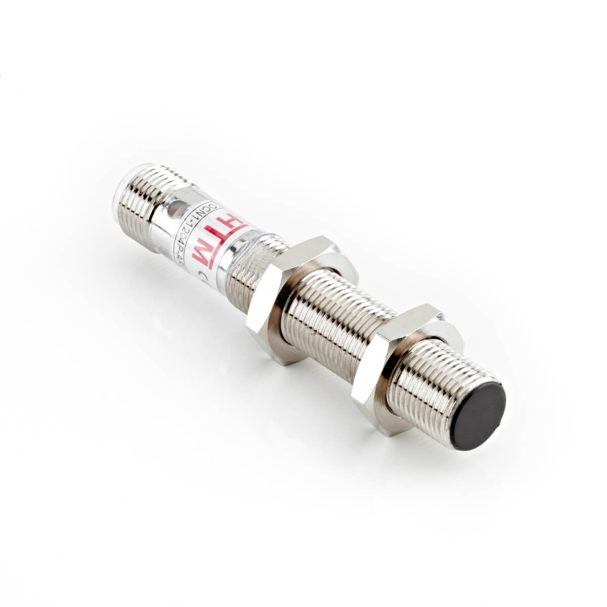
|
Shielded Tubular |
4mm |
Lateral (Side) |
0.8mm - 1mm |
| Shielded Tubular |
30mm |
Lateral (Side) |
10mm - 15mm |
| Unshielded Tubular |
6.5mm |
Lateral (Side) |
2mm |
| Unshielded Tubular |
30mm |
Lateral (Side) |
22mm - 29mm |
| Analog Tubular |
12mm |
Axial (Head On) |
8mm |
| Analog Tubular |
30mm |
Axial (Head On) |
25mm |
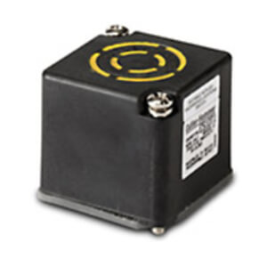
|
Shielded Limit Switch |
118x40x40mm |
Lateral (Side) |
13mm |
| Unshielded Limit Switch |
118x40x40mm |
Lateral (Side) |
24mm |
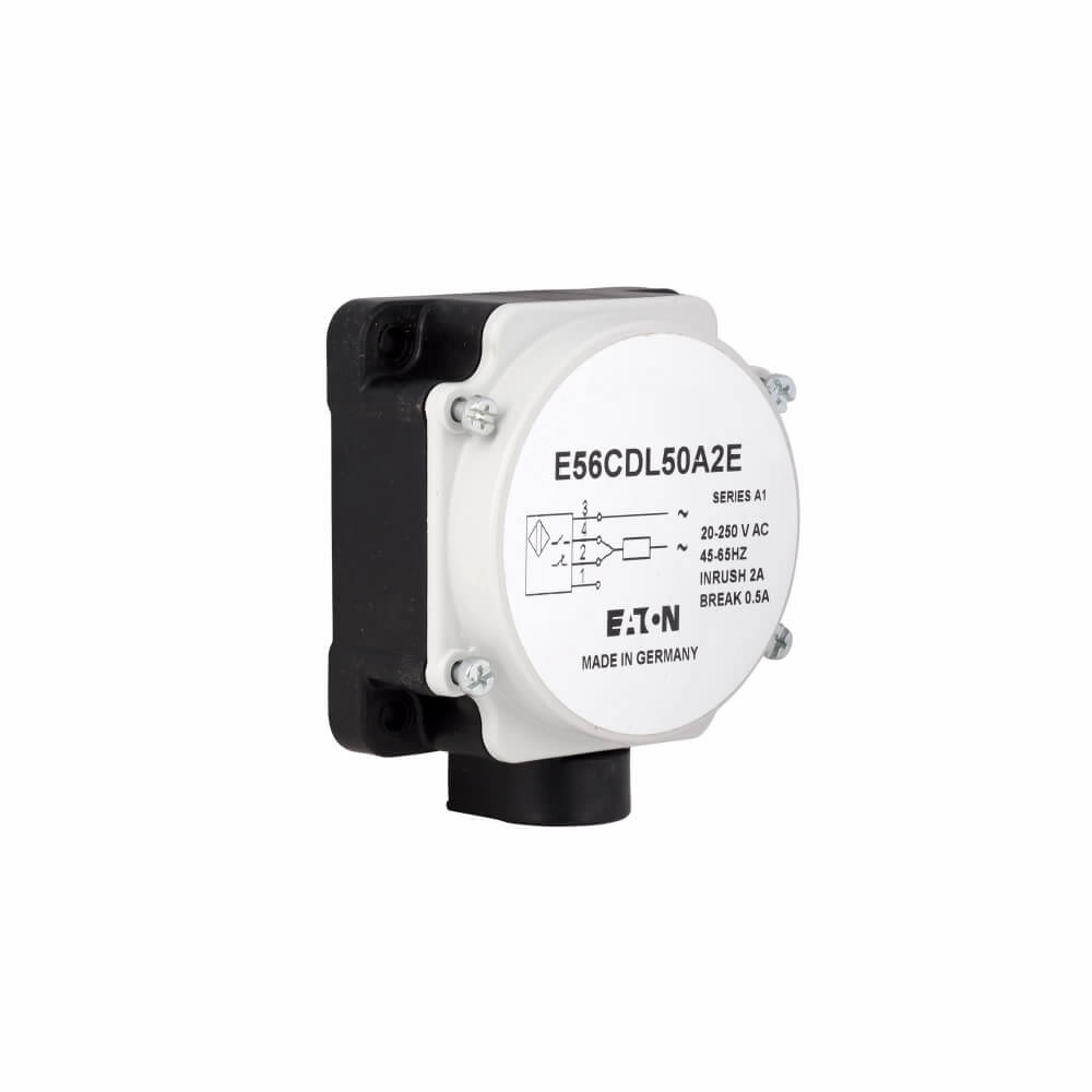
|
Shielded Long Range Pancake |
79x79X39mm |
Lateral (Side) |
40mm |
| Unshielded Long Range Pancake |
79x79X39mm |
Lateral (Side) |
100mm |
Tubular Sensor

| Sensing Style |
Size of the Sensor |
Approx. Max Sensing Range |
| Shielded Tubular |
4mm |
0.8mm - 1mm |
| Shielded Tubular |
30mm |
10mm - 15mm |
| Unshielded Tubular |
6.5mm |
2mm |
| Unshielded Tubular |
30mm |
22mm - 29mm |
| Analog Tubular |
12mm |
8mm |
| Analog Tubular |
30mm |
25mm |
Limit Switch

| Sensing Style |
Size of the Sensor |
Approx. Max Sensing Range |
| Shielded Limit Switch |
118x40x40mm |
13mm |
| Unshielded Limit Switch |
118x40x40mm |
24mm |
Pancake Sensor

| Sensing Style |
Size of the Sensor |
Approx. Max Sensing Range |
| Shielded Long Range Pancake |
79x79X39mm |
40mm |
| Unshielded Long Range Pancake |
79x79X39mm |
100mm |
What is an Extended Range (Long Range) Inductive Proximity Sensor?
An extended range sensor can detect metal objects two to three times farther away than a standard range sensor.
How Does the Target Material Affect the Sensing Range?
Because metals have different inductive properties, the type of metal will affect the distance at which an object is detected. See your specifications sheet for your specific sensor to get the
correction factor for your target metal and sensor size. Multiply the sensor range by the correction factor to get the range for detecting that target metal. Steel
targets can be detected from farther away than other metals. Copper targets affect the electromagnetic field less than other metals, so copper targets must be close to the
sensor to be detected. The chart below shows some typical values for correction or reduction factors for common target metals.
Correction/Reduction Factors for Typical Target Metals
| Target Material |
Corrective Factor |
| Construction Steel (400 series) |
0.90 - 1.00 |
| Stainless Steel (300 Series) |
0.65 - 0.85 |
| Brass |
0.35 - 0.50 |
| Aluminum |
0.35 - 0.47 |
| Copper |
0.30 - 0.40 |
How Does the Target Size Affect the Sensing Range of an Inductive Proximity Sensor?
Sensing Range or Rating Operating Distance specifications are given for a Standard Size Target, which is typically 1mm thick with a surface area equal to the larger of
the size of the sensor face or 3 times the minimum sensing range. Targets smaller than the standard target size will have a smaller sensing range.
Mounting Restrictions for Inductive Proximity Sensors
Inductive Proximity Sensors are offered in different sensor styles: shielded, semi-shielded, and unshielded (or non-embeddable). Shielded proximity sensors can be
mounted with the mounting metal touching the sensor. Semi-Shielded Inductive Proximity Sensors must be mounted with a metal free zone around the sensor.
Unshielded sensors or non-embeddable sensors must mounted with an even larger area around the sensor that has no metal.
Operation of a Limit Switch
What is a Limit Switch?
A limit switch is a sensor that is designed to change the state of a switch when an object moves past its limit. Limit switches are often used to count the number of objects
in industrial or commercial manufacturing or as safety interlock switches for doors.
How Does a Limit Switch Work?
There are two general categories of limit switches: a physical limit switch and an inductive proximity limit switch.
Physical Limit Switch
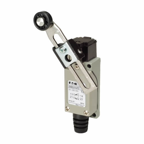
A Physical Limit Switch may sense an object using
physical contact when the object pushes the sensor actuator (whisker, lever, roller plunger) passed a "limit" which changes the state of the switch.
Inductive Proximity Limit Switch

An Inductive Proximity Limit Switch senses an object without contact using electromagnetic fields as described above for inductive proximity sensors.
How does a Capacitive Proximity Sensor Work?
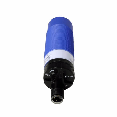
A capacitive proximity sensor can sense both metals and non-metals, including paper, plastic and liquids like oil, water or paint. The capacitive proximity sensor works without
physically contacting the object by creating a field around the sensor
using the dielectric principles of capacitance. When the object reaches an operate point, the capacitive proximity sensor detects the object by sensing changes in capacitance
between the object and the sensor. Ambient temperature changes and other nearby objects can interfere with detection using capacitive proximity sensors. Capacitive proximity
sensors can be used to detect product position in manufacturing plants, to measure brake disk deformation, and even to detect changes in fluid levels for monitoring toner levels in
printers.
How does a Photoelectric Sensor Work?
A photoelectric sensor uses light to detect the presence or absence of an object without actually touching the object.
Three common types of photoelectric sensors are diffuse reflective sensors, retro reflective sensors, and thru beam sensors.
Diffuse Reflective Photoelectric Sensor
A diffuse reflective photoelectric sensor detects the presence of an object by emitting a light beam and measuring the light reflecting off the object's surface.
A diffuse reflective sensor has the shortest sensing range of all photoelectric sensors.
Retro Reflective Photoelectric Sensor
A retro reflective photoelectric sensor, or reflex sensor, utilizes a special reflector that returns the light beam back to its sensor. An object
is detected when it interrupts the reflected light from reaching the retro reflective sensor. A retro reflective sensor has a medium sensing range.
Thru Beam Photoelectric Sensor
A thru beam photoelectric sensor has a separate emitter and receiver that detect an object when it interrupts the continuous light beam from the emitter to the receiver.
A thru beam sensor provides a maximum detection range and is ideal for sensing opaque objects. Maintaining the calibration of a thru beam sensor is critical
to ensure that the light beam transmitted by the thru beam light emitter reaches the thru beam receiver when not interrupted by an object.
Wiring for Sensors
2 Wire Sensor
A 2 wire sensor is intended to be connected in series with the controlled load. Because these sensors derive the power to energize their internal
electronics through the load they control, a minimum current is drawn through the load when the sensor is in the open state. This current is so small that it can
be ignored and will not turn on electromechanical devices such as relays and solenoids. However, this current could be enough to operate
an electronic load. Cutler-Hammer's 2 wire sensors have the lowest leakage current in the industry and are suitable for many electronic loads.
2 Wire AC NO (Normally Open) Sensor
3 Wire Sensor
A 3 wire sensor connects in parallel with the load they control, drawing power from a separate source for their internal electronics.
This prevents substantial current flow through the load when the device is open.
AC NO(Normally Open)/NC(Normally Closed) or DC PNP(Switched Positive)
Operation of Logic Modules
A proximity sensor detects the presence or absence of an object in its vicinity and communicates this information to logic modules, which use it to
make decisions or trigger specific actions in automated systems.
On Delay
Adjustable delay between the time an object is sensed and when the switch function occurs.
Off Delay
Adjustable delay between the time an object leaves the sensing field and when the switch transfers back to its non-sensing state.
On and Off
A combination of on delay and off delay adjustments.
Delayed Single Shot
Adjusts the length of time a switch remains in the "ON" cycle after an object is sensed, regardless of how long the object stays within the sensing field.
The "ON" cycle can also be delayed after the object is sensed.
Additional Reference Guides:
Warning: When using this information to perform electrical work, call a licensed electrician and consult the NEC® for safety.
All licensed electricians have passed examinations covering the National Electric Code®, know state and local building codes, and may carry insurance to cover damages.